Basic electric guitar circuits - part 3
(Switches and Output Jacks) by Kurt Prange
In Part 1, we discussed how pickups work. In Part 2, we discussed how potentiometers and capacitors work.
Now let’s take a look at how pickup selector switches and output jacks work.
Pickup Selector Switches
Most guitars have more than one pickup and each one has unique tonal characteristics depending on its placement,
construction and materials. The pickup selector switch allows the guitar player to choose between different
pickups or a combination of them. The pickup placed close to the guitar neck has a warm, smooth tone with more
bass content and is frequently referred to as the “rhythm” pickup, while the pickup placed close to the bridge has
a sharper, biting sound with more treble content and is frequently referred to as the “lead” pickup. Of course,
these are just generalizations. You might find that the neck pickup sounds sweeter for your leads or maybe you
get more rhythm crunch from the bridge pickup. The subjective nature of tone is one of the main reasons it’s
empowering to be able to customize your own instrument.
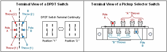
People are often confused by the switch terminology of “poles” and “throws”, but it’s actually quite simple.
The switch allows us to change the electrical continuity between its terminals. The “pole” is the name of the
terminal whose continuity is switched between one or more throws. As shown in the DPDT (double pole double throw)
switch drawing above, in position “1” there is continuity between “Pole A” and “A Throw (1)”. In position “2”
there is continuity between “Pole A” and “A Throw (2)”. This A-side alone could be thought of as an SPDT switch
because it has a single pole with two throws, but because we have an additional B-side the entire switch has two
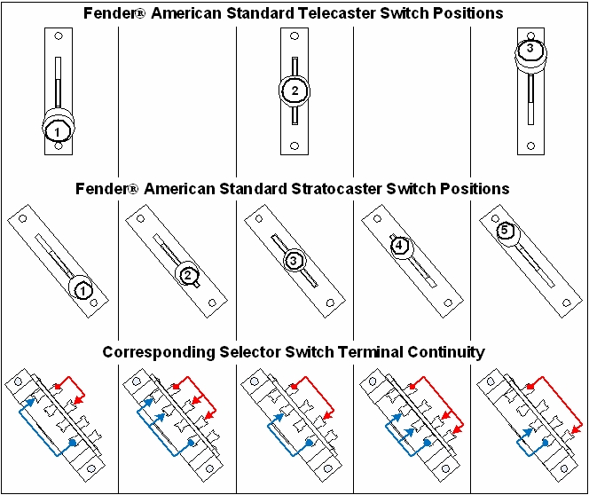
poles with each pole having its two respective throws (i.e. DPDT). The standard Telecaster switch could be
considered DP3T because it has two poles with each one having three throw terminals. The standard modern
Stratocaster switch adds two intermediate switch positions “2” and “4” (as shown below) where each pole has
electrical continuity with two of its respective throw terminals at once.
The standard Les Paul switch is shown below. In position “1” P(A) has continuity with T(A), but P(B) is
disconnected from T(B). In position “2” both P(A) and P(B) have continuity with their respective throws T(A)
and T(B). In position “3” P(B) has continuity with T(B), but P(A) is disconnected from T(A). The ground
terminal is used to connect to the common ground along with the potentiometers, output jack and the bridge in
order to eliminate popping and buzzing noises.
The Output Jack
The output jack allows us to connect the signal from the guitar to an amplifier. The standard guitar output
uses a ¼” mono jack having two terminals (as shown below) which make contact with the mono ¼” plug end of the
guitar cable. The “tip” terminal is connected to the output signal and the “sleeve” terminal is connected to
the guitar’s common ground. This is standard for amps and effects pedals, too.
Wiring Diagrams
It’s easy to find electric guitar wiring diagrams on-line through the websites of guitar and pickup
manufacturers. There are also a lot of popular modifications out there that you might like to try out.
Once you understand the basics of how these circuits work, you can even get creative and customize an original
circuit that suits your style best. You won’t have to feel locked into your standard set up ever again. If you
come across a new trick that you think you might like, heat up your soldering iron and try it out.
Basic electric guitar circuits - part 1 (Pickups)
Basic electric guitar circuits - part 2 (Potentiometers and Tone Capacitors)
Kurt Prange (BSEE) is the Sales Engineer for
Amplified Parts in Tempe, AZ. Kurt began
playing guitar at the age of nine in Kalamazoo, MI. He is a guitar DIY’er and tube amp designer who
enjoys helping other musicians along in the endless pursuit of tone.