Negisters, Unijunction transistors, Precision Resistors, and Hall Effect Devices
Nothing has impacted our lives more than the electronic devices we now use in our everyday lives.
More and more, sophisticated devices are becoming commonplace and research is constantly adding to
the list. Some of the new devices are the result of new technology while others are just new techniques
applied to conventional devices.
Negistor
One of the most unusual devices in electronics is the negister. A common NPN transistor can be
turned into a negistor by wiring it in reverse. The emitter is connected to the power source through
a resistor and the collector is connected to ground. When wired this way the transistor exhibits a
phenomenon known as negative resistance, also known as avalanching.
In the diagram we see a capacitor across the transistor charges until the reverse breakdown
voltage is reached. At this point the collector to emitter resistance actually reaches a resistance
of less than zero and then the capacitor is discharged through transistor. Once the capacitor is
discharged the transistor returns to its resistive state and the capacitor starts to charge again.
Not all transistors will operate in this mode, however, a surprisingly large number do. Even
transistors that test bad may operate as negisters.
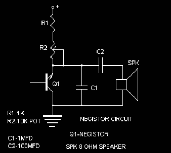
Amazingly, the circuit is extremely stable and produces a linear ramp wave. It can feed a
speaker directly or, an amplifier stage can be added to use the oscillator as a function generator.
Its wide range and stability make it suitable for use in music synthesizers. The components used
in the circuit are just a starting point, for different transistors will react differently and you
may have needs that require other component values so experiment. It is advisable to use a regulated
power source of at least15 volt.
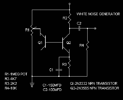
White Noise Generator
The avalanche mode can also be useful in the production of white noise. The illustration shows
a transistor Q1 connected differently than the oscillator. Instead of the emitter lead, the base
of the transistor is used and since there are no frequency-selecting components, a cascade of
random frequencies is generated. Transistor Q2 amplifies the signal using resistor R2 as a current
limiter, while R3 and capacitor C1 smooth response and increase the overall gain. Potentiometer
R1 will customize the drive current to obtain the best results from a particular transistor. It
should be adjusted to get the maximum volume. White noise is all frequencies at the same level
and it is used in electronic music production as well as a tone source for audio testing.
Unijunction Transistor
One of the most unusual solid state devices is the unijunction transistor. Conventional
bipolar and FET transistors use a base or gate lead to control the resistance between the 2
remaining leads. Unijunction transistors do not operate like other transistors. Unlike other
transistors, The unijunction transistor actually passes the input signal through to ground.
This makes it suitable only as a wave shape generator. It produces a negative pulse at base 1
and a reverse exponential ramp at the emitter.
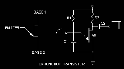
In the unijunction circuit capacitor C1 charges through resistor R1. When a trigger
voltage is reached (approximately 1.3 volts), the capacitor is discharged through base 2.
Capacitor C2 charges through resistor R2 and is discharged at the same time as capacitor
C1, producing a negative pulse. The schematic symbol of a unijunction transistor looks
like an FET except for the input lead which turns down, indicating the capacitor
discharge to ground function.
Because the unijunction transistor is not a linear device, an FET amplifier stage
is required to produce a linear ramp. Because of the complex harmonic content of a linear
ramp, It is more useful as a synthesizer tone or test tone.
Precision Resistors
There are times when a specific value resistor that falls outside the normally available
values. You can use a trimmer potentiometer, however, the exact value may be hard to tune and
vibrations can change the setting. Precision resistors are available commercially but again they
may not be the exact value you need. Because of new components and more demanding circuit
designs, the need for precision resistors is growing.
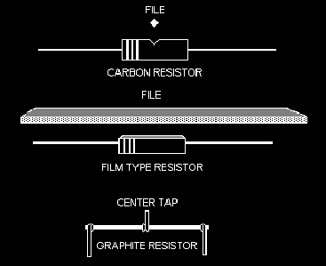
One way to make you're own precision resistors to file them down. The illustration shows
how to prepare carbon and film type resistors. Choose a resistor that is closest to but
greater in value than you need. In the case of a carbon resistor, use a square or triangle
file and work it across the resistor to cut a groove the resistor. Connect the resistor leads
to an ohmmeter with alligator clip-leads, to monitor the change in resistance. Film type
resistors should be filed using a flat file.
Soldering the resistor tightly in place on the circuit board and gently filing the resistor.
Is one way to simplify the process. When you have achieved the proper value, clean away the
excess particles and then coat the resistor with airplane glue to keep out moisture.
Another way to make your own resistors is to use pencil lead or graphite. Even the
resistance of a line on a piece of paper can be measured on an ohmmeter. Wire wrapped
around a pencil lead can function as a resistor. Shrink-wrap will operate as an insulator
or again use airplane glue. Even center-taped resistors can be made from pencil lead.
Different number pencils, such as a number 2 will act differently than a number 4, so
again experiment.
Hall Effect
In 1879 an American physicist Edwin Hall experimented with magnetic forces and their
effect on wire and metal surfaces. His work led the way for research that resulted in a
number of devices that are important to modern digital technology.
If a conductor carrying an electrical current comes in contact with a magnetic field,
a voltage, known as the Hall voltage, is generated across the conductor. The magnetic
field distorts the natural flow of electrons through the conductor.
In 1985, German physicist Klaus-Olaf von Klitzing won the Nobel Prize in physics for
his expansion of Hall effect principals to semiconductor technology and discovered the
quantum Hall effect.
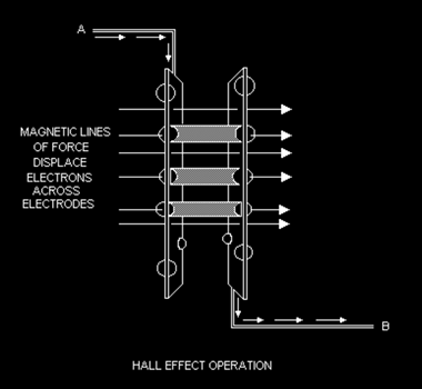
In the diagram we see how magnetic force displaces charged particles from one electrode
to another, carrying with it, a flow of current from point A to point B. Early experiments
in the development of the Hall effect sensor were not very successful. Semiconductors are
made of electrons and holes that are naturally attracted to each other.
Triggering a current flow through semiconductors with magnetic force was far too
marginal and unstable. With the development of artificial semiconductor structures, a
matrix was designed to hold electron and holes in thin layers of material separated by
a barrier layer.
With careful attention paid to new doping ratios and new material, the right
chemical combination was found and a practical Hall effect sensor prototype was built.
Further improvements, such as signal amplification, differentiate signal levels to
assure a digital output.
Although a Hall effect sensor acts like relays, it has two specific advantages.
The first is no bounce, like the mechanical relay and the Hall effect sensor can
operate at very high frequencies.
Hall Effect Sensor
The package for the Hall effect sensor is very much like a transistor. It is
a three lead in line device in a transistor size black plastic case. Some manufacturers
also have a surface mount model. The only difference is a transistor has a curved back
while Hall effect sensors are flat. Inexpensive devices that I picked up in a surplus
store had a circle on the front, indicating the side that is to come in close proximity
to a magnetic source.
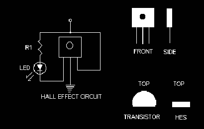
In the basic circuit we see an LED with current limiting resistor. When a magnetic
source is brought close to the HES, the LED turns on. The backside of the sensor will
respond to the opposite pole of the magnet.
Alarm
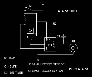
Hall effect sensors can be used to trigger alarms. The alarm circuit illustration
displays a simple alarm. A magnet should be placed so it passes near the sensor when
opening a drawer or door of a locked enclosure. Once triggered the alarm will stay
on until switch S1 is turned off. To reset just turn the switch back on.
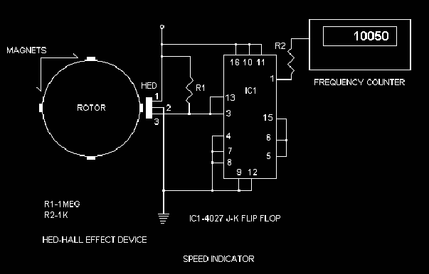
Motor Speed Indicator
One of the most useful functions that the sensor can perform is a motor speed
indicator. In the diagram we see 4 magnets added to the rotor of a motor and a
sensor fixed in close proximity. As the magnets pass by the sensor, it clicks
on momentarily, 4 clicks equal one, turn in this case. A 4027 J-K flip-flop
divides the clicks by 4 to provide an accurate spin count that is then fed to a
frequency counter.
There are a wide variety of frequency counters on the market: large expensive
test bench units and small circuit boards that can be incorporated in your designs.
They are available from most electronic surplus or supply companies.
Conclusion
Although Hall effect sensors are not exactly standard at your local supplier,
you might try Allegro MicroSystems, in Worcester, Mass or All Electronics Crop,
PO Box 567, Van Nuys, CA 91408. Some manufacturers of motors are including sensors
in their new designs, anticipating the demand for high tech motors for new products,
so you should also check with them. There is a sense of satisfaction that comes with
making your own components or enlisting an unusual application of a conventional device.
It may also stimulate your imagination and awaken the mad scientist within you. So get
to your lab and experiment, experiment, experiment.
by Terence Thomas (t1t7t91@yahoo.com)