Building a fusion reactor in a basement workshop
Philo Farnsworth is best known as the inventor of television. That’s certainly an impressive
accomplishment by itself, but he also created a nuclear fusion reactor called the Farnsworth–Hirsch Fusor.
It evolved out of his work with various types of television tubes and his observations of their effects.
Although he achieved a sustainable fusion reaction with it, he was not able to generate electricity as he
hoped - although that still remains a possibility.
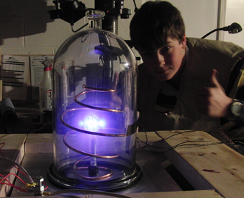
William Jack is a young scientist experimenting with the Farnsworth Fusor and shares his fascinating project
with us.
Q. What got you started in the Fusor project?
A. I have been interested in engineering and physics as long as I can remember. I began building large scale
projects such as replica catapults and a myriad of other things in around 5th grade. Prior to that I had mainly
worked in the domain of the lego brick. Last summer I came across a website called the Open Source Fusor Research
Consortium, a website where a few people share their work on fusors and research on them. After reading the forums
intently for about a month, I decided that I had amassed enough knowledge to build a fusor and that building one
as a soon to be 9th grader was not entirely unrealistic. I then proceeded to collect parts, design and build a
demonstration fusor: essentially a fusor lacking a system to create a deuterium (hydrogen-2) atmosphere. This does
everything a "fusing" fusor does, however in an atmosphere consisting of a gas other than deuterium.
Q. What were the most difficult challenges in building it?
A. I faced a multitude of challenges when building the fusor, and the difficulty of the challenges made this project
extremely fun. When I began building the fusor, I was a complete newb to both vacuum systems and high voltage
systems, essentially the heart of any fusor project, and that in itself was a challenge. Overall, the entire
project was a challenge.
Q. What types of radiation do you need to be concerned about?
A. When operating a fusor, you need to be aware of two types of radiation: fast neutron radiation caused by the fusion
reaction, and bremsstrahlung x-ray radiation caused by the slowing down of electrons. The primary cause for concern
is the x-ray hazard, X-rays will begin to shine through viewports and other glass surfaces at around 12,000 volts
of input voltage (this is why cameras and mirrors are used to look through viewports), and they will begin to
penetrate stainless steel at around 40,000 volts. At the point that they begin to shine through anything, it is
wise to shield that area with lead. Generally for most fusors, neutrons are not typically a worry unless you run
your reactor to the point where it emits multiple hundreds of thousands of neutrons per second. At that point, it
is usually wise to shield the fusor with a shield made of parrafin wax or boron dissolved in water.
Radiation is not a dangerous aspect of operating a fusor is ordinary circumstances for a number of reasons.
First is that the radiation is emitted isotropically, in other words, in all directions. This means that as you
get farther from the fusor, the radiation strength drops with the square of the distance from it. This means
that you only have to be a few feet from the fusor to minimize your radiation dose.
Another factor contributing to the safety of the fusor is that they are typically run for only a short period of
time, as they are rather "finicky" to operate. Most people do less than an hour high power fusion every month.
Thus minimizing radiation exposure.
Q. Have you taken radiation measurements and confirmed that the fusion reaction occurred during operation?
A. My fusor is currently only a demonstration fusor, and as I explained above, no detectable fusion reactions
are occurring. HOWEVER, My current project is the rebuild of my demonstration fusor into a fusing fusor complete
with DC magnetron Ion source, 50,000 volt power supply, deuterium system, and ultra-high vacuum system
Q. Do some of your friends or family think you’re a little nuts to be interested in this and doing it?
A. Although the things I do are certainly abnormal, I am not considered crazy by family, neighbors, or friends.
I have explained to them that the fusor is not a particularly dangerous project (however some HV systems,
especially those containing multiplier stacks and filter capacitors can "bite"). I use MANY safety precautions
when I run my fusor (I am joking about the "duck and cover" in my video, I use a very strong pyrex bell jar),
from a lead vest I wear, to keeping one hand in my pocket when working on the HV systems.
Q. Is there a ‘next phase’ to this project?
A. Oh yes, there is. I am currently building a fusor with a spherical stainless steel chamber complete with high
vacuum flanges, a 50,000 volt power supply based on an x-ray transformer (I also am building a 30kV lines
frequency neon sign transformer voltage doubler made from microwave capacitors and diodes, should I fry the x-ray
transformer), a diffusion pump based high vacuum system that should allow me to hit pressures of below 1
millitorr, which equates to less than 1/760000 of atmospheric pressure, a deuterium injection system based on a
5 micron wide laser drilled flow orifice, and a neutron detection system based on either a boron-10 lined tube
or based on the detection of beta decay from neutron activation. Details of this system can be found on my blog
at www.tidbit77.blogspot.com.
Q. What are the most fascinating things that you’ve learned from this?
A. By building and operating a fusor, I learned many things about working with high voltage, high vacuum,
radiation detection, and many other things. Some of the most interesting things I learned involved the
interactions of plasma at different pressures, and voltages.
Explanation:
Inertial electrostatic confinement nuclear fusion reactors (the fancy name for Farnsworth and Hirsch-Meeks Fusors)
are actually not very complicated in the way that they work, albeit the difficulty involved in building one that
does work. Basically, a fusor consists of two concentric, usually spherical grids inside a vacuum chamber, the
inner one usually about 5 times smaller in diameter than the outer, (most fusors use the vacuum chamber itself
as an outer grid). A vacuum of about 1 millitorr (the exact pressure varies from fusor to fusor) is pulled on the
vacuum chamber, and then it is backfilled with deuterium to a pressure of about 5 millitorr or less. The inner
grid is then charged with anywhere from -20,000 to -100,000 volts at a current of at least 2 mA, the outer grid
is left grounded. Due to a process called electrostatic field emission (from the inner grid), the deuterium is
ionized. These ions are positively charged, which results in them being accelerated towards the negatively
charged inner grid wires. Some ions strike the wires, and others carry on through the grid. Some of the ions
that pass through the grid collide, and some of those collisions result in the fusion of the deuterium ions into
helium.
Essentially, what I have built is a plasma discharge device that operates in the same way as an IEC nuclear
fusion reactor; the only difference is that my device lacks a system to backfill the vacuum chamber with
deuterium, the fuel for fusion, a system like mine is known as a demo fusor. My demo fusor consists of two main
systems: the high voltage system and the vacuum system. The vacuum system pulls a vacuum with a mechanical pump
on a 6” diameter Pyrex bell jar placed on top of a machined aluminum base plate. The pressure reached is around
100 millitorr (1/76,000 of atmospheric pressure). In order to measure the vacuum pressure I use a thermocouple
vacuum gauge, similar to one used in HVAC repairs. The electrical system for my demo fusor consists of a neon
sign transformer (without ground fault protection) that outputs 15kV AC at 32 mA, this is full wave rectified by
an oil immersed rectifier made from two microwave oven diodes. Voltage and amperage metering are done by
oil-immersed electronics as well. This power supply will put out around 7kV DC. The inner grid in my fusor is
attached to a sparkplug-turned high voltage feedthrough, and it is made out of stainless steel wire that is
twisted together into loops, essentially it is all pressure fit. The outer grid is made from ¼” solid copper wire
bent and soldered into a spherical shape, I also have another outer grid made of the same material but bent into
a spiral shape.
I am currently building “Jack Fusor Mk. II” which I aim to achieve fusion with. My new power supply will be a
rectified 75 kV transformer out of an x-ray machine. This should provide me with around 50 kV of DC power at
2.75 mA of current. X-ray transformers are notoriously easy to fry, so I am also building a supply based on two
neon sign transformers (oil immersed with floating cases) in parallel run through a Villard type voltage doubler
circuit; this should put out around 30kV at a much higher current than the x-ray transformer setup. My new
vacuum setup will allow me to reach pressures of less than 1 millitorr. It will include a better mechanical
pump, coupled with a special high vacuum pump called a diffusion pump. For my new chamber, I am using a
spherical chamber 6” in diameter with special Conflat flanges; specifically designed for high vacuum. My
deuterium for this setup will be leaked into the chamber through a laser drilled orifice 6 microns wide. In
order to detect neutrons from fusion, I will either use a boron-10 lined proportional tube read by NIM bin
equipment, or I will neutron activate silver foil and then measure the beta decay of the silver with a Geiger
counter. Of course, everything will be shielded with lead and paraffin (or borax dissolved in water).
Effects of an Outer Grid on the Plasma
Produced by an Inertial Electrostatic Confinement Nuclear Fusion Reactor
In order to understand this project and its importance, one must understand what an Inertial Electrostatic
Confinement (IEC) Fusor is. An IEC Fusor is a device used for research purposes to produce a plasma discharge,
or fuse deuterium into helium via the process of D+D inertial electrostatic confinement nuclear fusion
(the fusor used in the experiment did not do the latter), by accelerating ions. The experiment investigated how
an outer grid affected the intensity of the light given off by the plasma produced, which, in turn, can give a
representation of the fusor’s efficiency. It was hypothesized (incorrectly) that the light intensity of the
plasma would be greater with an outer grid in place. Through controlled, precise experiment and accurate data
analysis, a definitive answer of the effects of an outer grid on an IEC fusor was reached.
The fusor was first built for the enjoyment of its creator; however it was decided to gather data from it in
various ways and present findings in a science fair project. Through extensive research, it was found that
nobody who had built a fusor had conducted a controlled experiment dealing with the outer grid’s affect on the
plasma and the efficiency of an IEC fusor. This finding was an influence on the decision to research this topic.
It was initially hypothesized that the plasma would be brighter with an outer grid.
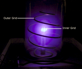
Inner and outer grids used in this experiment
In the experiment, a high vacuum of 150 millitorr (as indicated by the thermocouple vacuum gauge installed in
the fusor’s vacuum system) is maintained between two concentric spherical grids within a bell jar, on top of a
grounded 6061 aluminum base plate. The inner grid is spherical, 1.5” in diameter and is constructed of six
vertical circles of stainless steel .032” wire. The circles of wire intersect at two distinct points, 180 degrees
from each other and collinear with the y-axis of the HV feed through. This inner grid is charged to about -2500
volts DC at 15 milliamps of current by a 15kv neon sign transformer. The outer, grounded grid is made of ¼”
copper rod bent into a helical spiral in the shape of a sphere 5.5” in diameter. This creates an inertial
electrostatically confined plasma discharge within the inner grid. In order to determine the properties of the
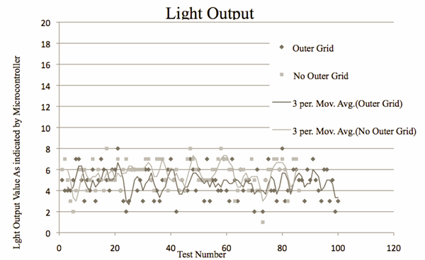
plasma, a sensor system was designed that utilizes a computer receiving data from a Picaxe 28x1 microprocessor.
The microprocessor, reading a light dependent resistor, converts the sensor’s analog signals to digital signals
ranging from 1-255, the greater the number, the brighter the plasma. One-hundred readings were taken with this
sensor system with the outer grid, and one-hundred readings without the outer grid were taken and recorded.
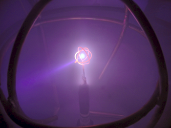
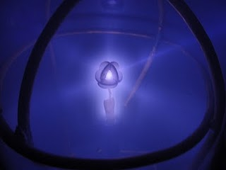
The picture shows a prime example of a plasma discharge in the fusor, using different grids than the ones
utilized in the experiment. The inner grid is glowing red due to ion bombardment, and the plasma inside the
grid, the poissor, is clearly visible along with a particle beam running into (or out of) the poissor.
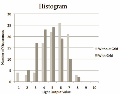
The data shows little skew, minimal variance, and the T-Test’s p value indicates that changing the independent
variable resulted in a change in the dependent variable (it is less than .05.) The data also shows that there
was a slightly higher light intensity when the outer grid was removed.
| |
(with outer grid) |
(without outer grid) |
| Standard Deviation |
1.441 |
1.601 |
| T-test |
0.008 |
0.008 |
| Mode |
5 |
6 |
| Median |
5 |
5.5 |
| Mean |
4.73 |
5.27 |
| Minimum |
2 |
1 |
| Maximum |
8 |
8 |
It was surprising when the results of the experiment disproved the hypothesis, and it was contemplated why the
tests without an outer grid generated a more intense light than the tests with the outer grid. After critical
review, it was concluded that the light given off by the plasma was less intense when the grid was in place.
This is because electrons were being drawn directly towards the grounded copper grid, a far better electrical
ground than the 6061 aluminum base plate (6061 aluminum creates an oxidation layer in the presence of oxygen,
thus inhibiting its electrical conductivity.) Therefore fewer electrons were available to remix with ions to give
off light from the plasma discharge; meaning the ions were reaccelerated more. This means that the fusor is more
efficient with a grounded outer grid in place. In the test without a grid there was less grounded, highly
conductive surface area close to the inner grid for the electrons to be drawn to, and therefore the ions remixed
with many electrons more quickly. Thus a discharge giving off more intense light was sustained. Because the
recombined electrons and ions have to be re-ionized and reaccelerated towards the inner grid, opposed to simply
being reaccelerated in the fusor with an outer grid, energy is wasted, thus, operating a fusor with an outer grid
renders it more efficient.
From this critical interpretation of the data it can be concluded that removing the outer grid from an IEC fusion
reactor results in a more intense light given off by the plasma and results in a decrease of the fusor’s
efficiency as a whole. It can be inferred that this is because of increased electron and ion remixing, which is
what creates the light given off by the plasma discharge. I plan to continue my research by studying the outer
grid’s effect on neutron fluxes, which represent the rate of fusion occurring in the fusor, in a neutron
producing fusor.
Sources Cited
4HV.ORG. Web. Fall 2010. http://www.4hv.org.
'Nuclear Fusion.' Nuclear Fusion. Web. Fall 2010.
http://hyperphysics.phy-astr.gsu.edu/HBASE/NucEne/fusion.html.
The Open Source Fusor Research Consortium II. Web. Fall 2010.
http://www.fusor.net.
'Safety Guidelines for High Voltage And/or Line Powered Equipment.' Sci.Electronics.Repair FAQ: Home Page.
Web. Fall 2010.
http://www.repairfaq.org/sam/safety.htm.
'Sam's Laser FAQ - Amateur Laser Construction.' Sci.Electronics.Repair FAQ: Home Page (LaserWiki.Org)
Mirror - Germany). Web. Fall 2010.
http://www.laserfaq.org/sam/lasercon.htm.
Acknowledgements
- Thank you to Eric Hahn for donating a Welch 1399 vacuum pump to help me with this project.
- Thank you to Tom Egan of Mercury Machining Company for machining my base plate for me.
- Thank you to my parents for supporting me through this process.
- Thanks you to the people who devote their time to the science fair.